Electronics
Overview
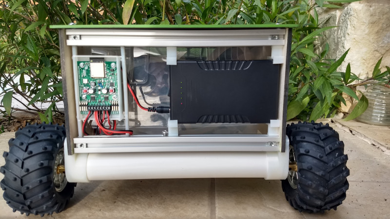
The control module for Growver 2020 was deliberately kept very simple. There are only 46 components on the board (compared to over 200 on other Growver designs).
- ESP32-WROOM SoC Processor with Wifi
- DC motor control (2 channels)
- Speed and direction control
- Current limited
- Controlled 12V output (for pump etc).
- On/off push switch
- Mode push switch
- UART for control commands
- RGB LED for status
- LED indicator for power
- I/0 lines for I2C, Tach, GPIO, RC servo, etc. (7 total)
Specifications
| Parameter | Value |
|---|---|
| Input voltage | 8-14 Vdc |
| Absolute max input voltage | 17 Vdc |
| Nominal motor voltage | 12Vdc |
| Max motor current (peak) | 3.6A |
| Nominal power output voltage (pump) | 12V |
| I/O Voltage logic level | 3.3V |
Design Files
Get the complete control module design zip file.
| File Description | File Type | Revision |
|---|---|---|
| Control Module Schematics | A | |
| Control Module PCB | A | |
| Control Module Schematics | PADS Logic | A |
| Control Module PCB | PADS Layout | A |
| Control Module Gerber Files | RS274X | A |
| Bill of Materials | xlsx | A |
Theory of operation
The control module accepts a 12V nominal power source. To keep it safe and simple, Growver uses at 12V 6000mAh lithium power bank ($30 on Amazon including a charger). The only draw back is that the unit has an LED internal battery level indicator the will gradually drain the battery over a couple of weeks if not switched off.
There’s no input protection on the control PCB. The battery bank has it’s own protection and it didn’t seem worthwhile to add reverse polarity, over-voltage or current protection. If a different battery pack is used, appropriate protection circuitry should be added in-line.
The on-off circuit is a variation of a common Schmitt trigger based, self-latching circuit that exploits the high operating voltage of 4000 series CMOS logic. It’s one of the very few things 4000 series logic is still useful for. The Rev B design will add a diode in series with the enable signal to U1, a buck converter. The diode blocks current from U1’s internal pull-up, which impacts the hysteresis of the latching circuit, especially when the battery voltage is over 13V.
A TI buck converter (U1) creates a 5V rail with up to 0.5A output. Enough to run the board and a small servo or auxialliary circuit. A Raspberry Pi or other device will need a dedicated buck converter. The logic rail is a simple linear regulator - efficient enough for this application.
Motor control uses another TI device, a DRV8870 Brushed DC motor controller. Very straightforward to use - especially with a range of integrated protection features.
The ESP32 SoC should need no explanation. More details on this powerful wireless SoC cane be found on the Espressif website.
There’s a WS2813 RGB LED for status. Since ESP32 pins are in short-supply, controlling 3 LEDs with a single pin is nice.
Lastly, a high-side 12V power switch can be used to switch loads up to 3A max. In Growver, this is typically used to control a 12DC pump.
The PCB is a simple 2-layer design. The thermal layout for the power ICs isn’t perfect, but entirely adequate for Growver. The supply current from the battery pack sets the upper limit for overall power of the system.